Element Group
The Element group is located at the very top of the modeling mode and is a collection of properties related to each element (Vertex, Edge, Face, and Object).
Change the element to edit.

In Modeling mode, the original mesh, Source Mesh, can be edited after selecting elements.
There are three editable elements (Vertex, Edge, Face) and an Object to exit the editing state. You can choose which element to edit through the icons at the top of the scene.
Depending on the selection of elements, there are properties within the Element group that are commonly applied to all, as well as properties that vary according to each specific element.
Through the pages dedicated to each element below, you can easily find descriptions of each element and the properties that vary depending on the element selected.
📄️ Vertex
📄️ Edge
📄️ Face
📄️ Object
📄️ Isolation
Shortcut Shift+ClickDrag
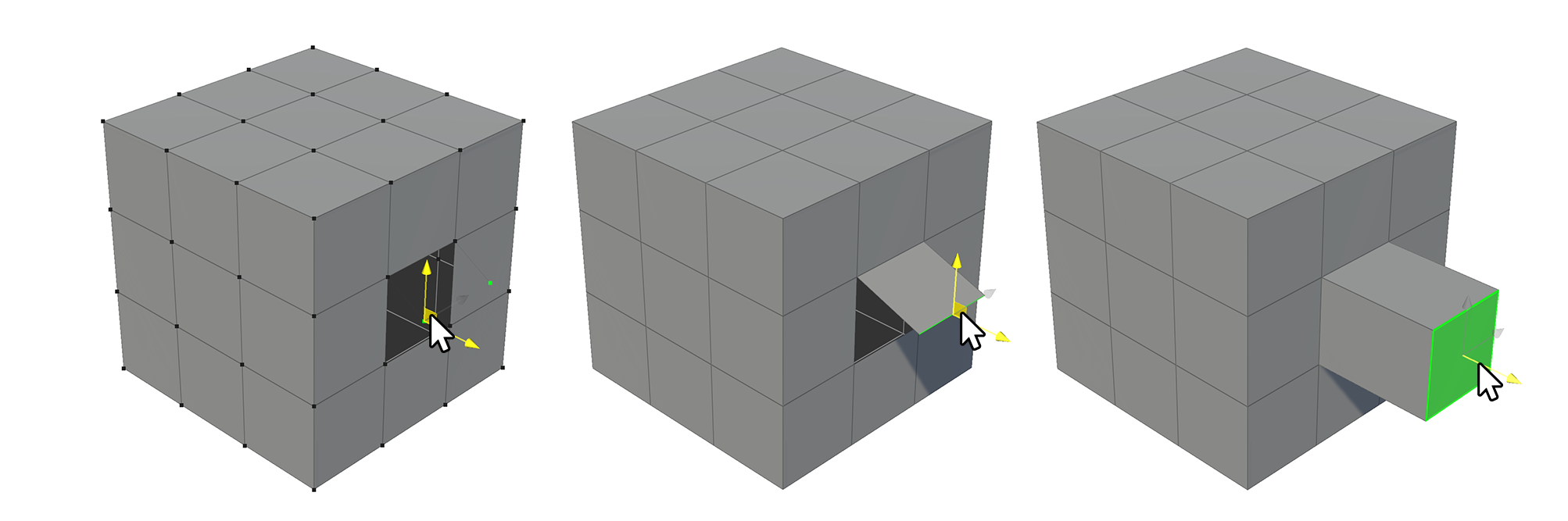
After selecting each element (vertex, edge, face), you can create new elements in a protruding or pushing manner in the direction of movement by moving the selected elements using Shift+click-drag.
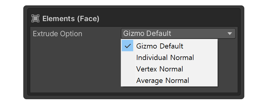
For face elements, you can choose how the faces protrude using the Extrude Option property within the Face Element group properties.
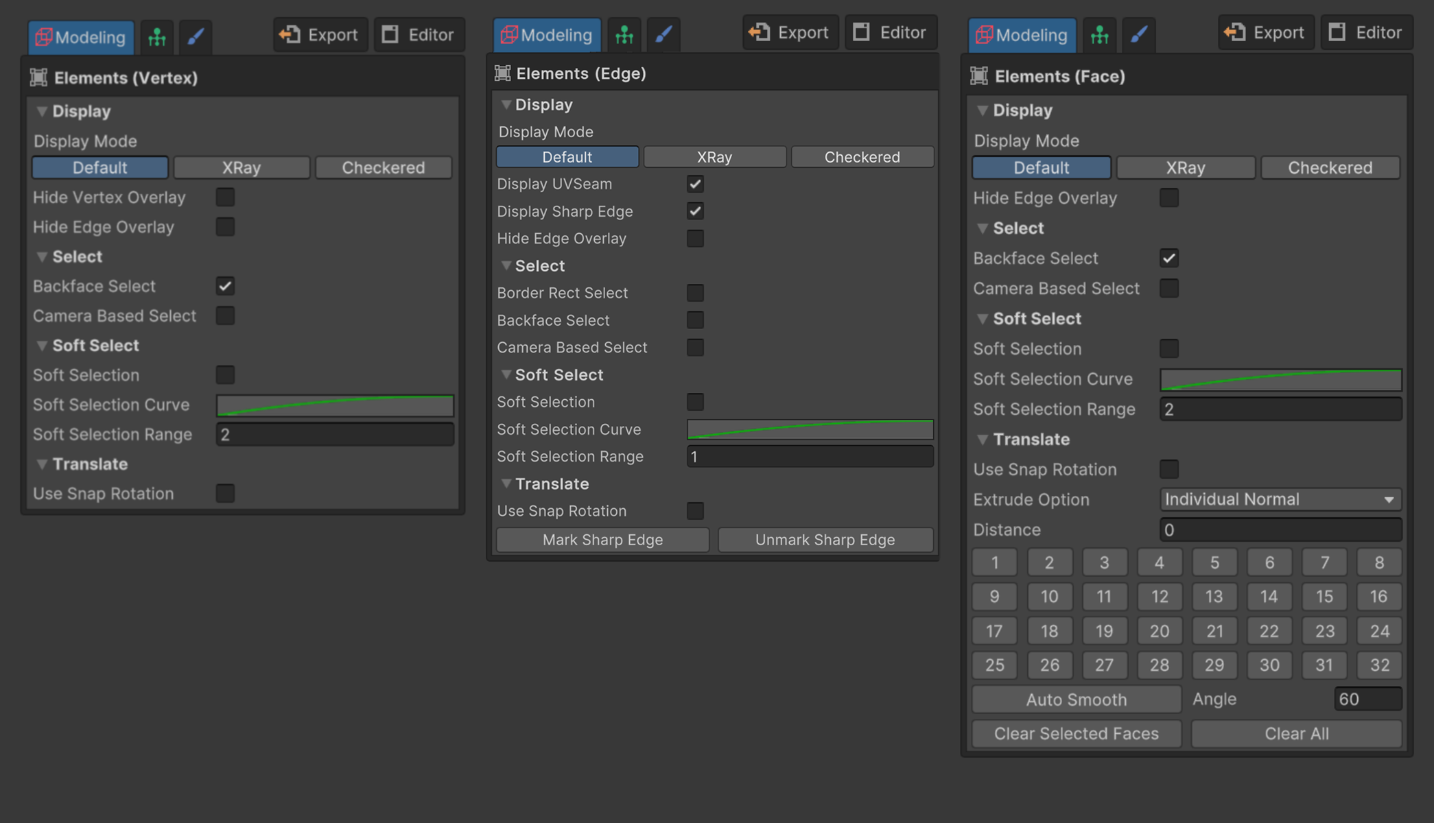
Common Properties
These are the properties that are commonly applied to each element within the Element group.
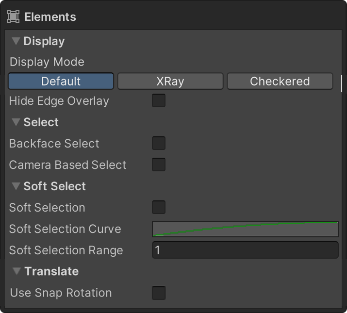
Display
This is a property that allows you to choose the display mode of the mesh.
XRay Mode
Displays faces as translucent.
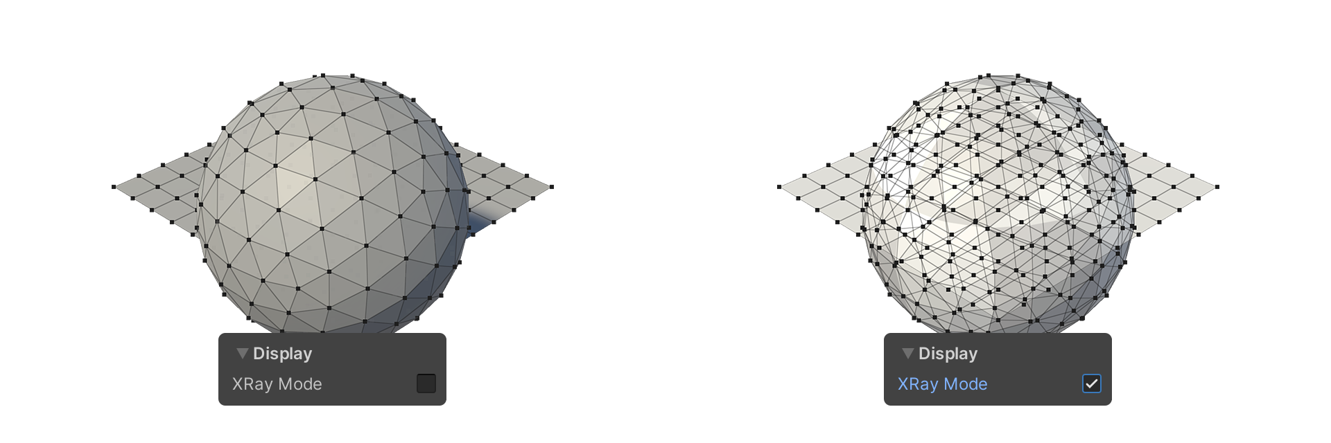
Using the XRay Mode property, you can easily view elements located on the backside of complex models.
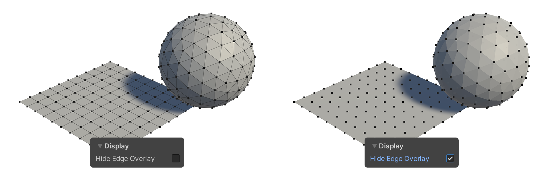
Hide Edge Overlay
Makes edges visible or hidden.
Select
This is a property that allows you to set the selection mode for elements.
Backface Select
You can set whether to select elements that are facing the opposite side.

When the Backface Select property is turned off, elements facing the opposite side are not selected.
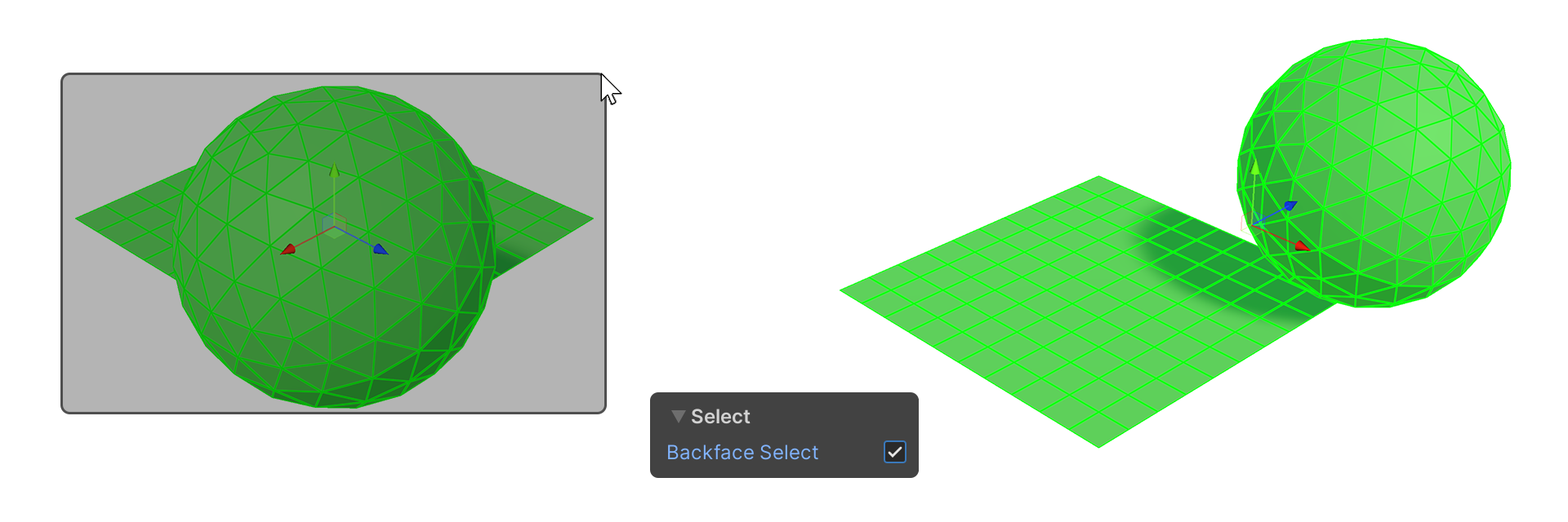
When the Backface Select property is turned on, elements facing the opposite side are also selected.
Camera Based Select
This is a property that allows for the selection of only the elements currently visible from the camera's perspective.

When the Camera Based Select property is turned off, elements obscured by the camera are also selected.
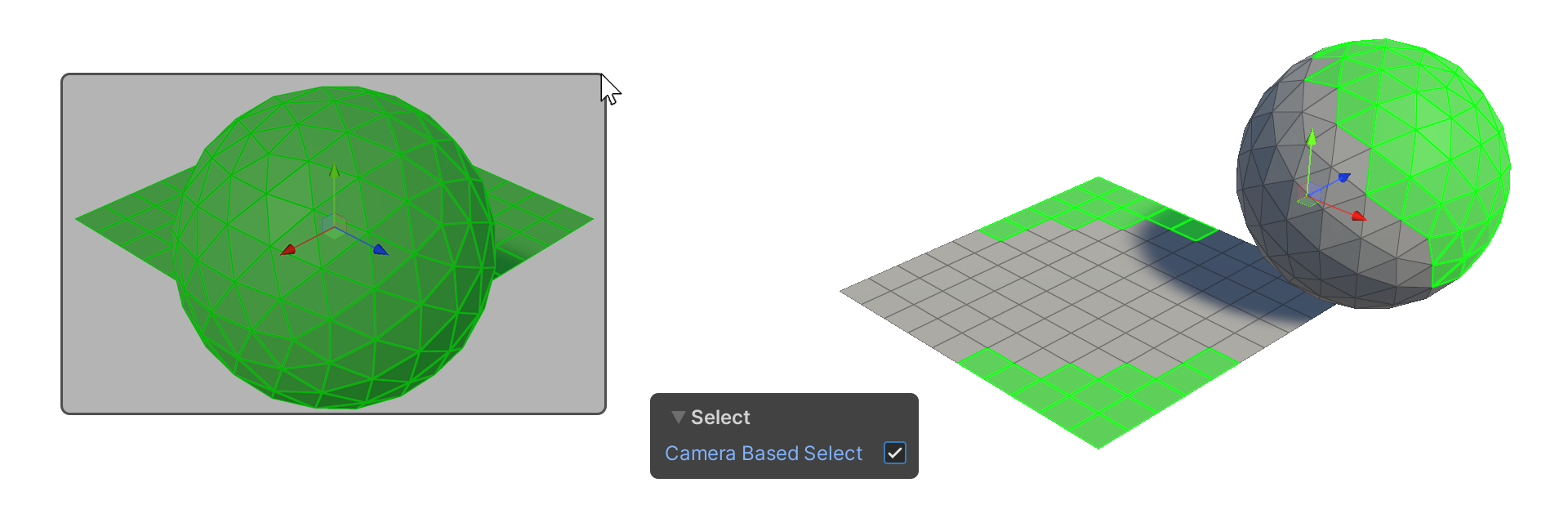
When the Camera Based Select property is turned on, elements obscured by the camera are not selected.
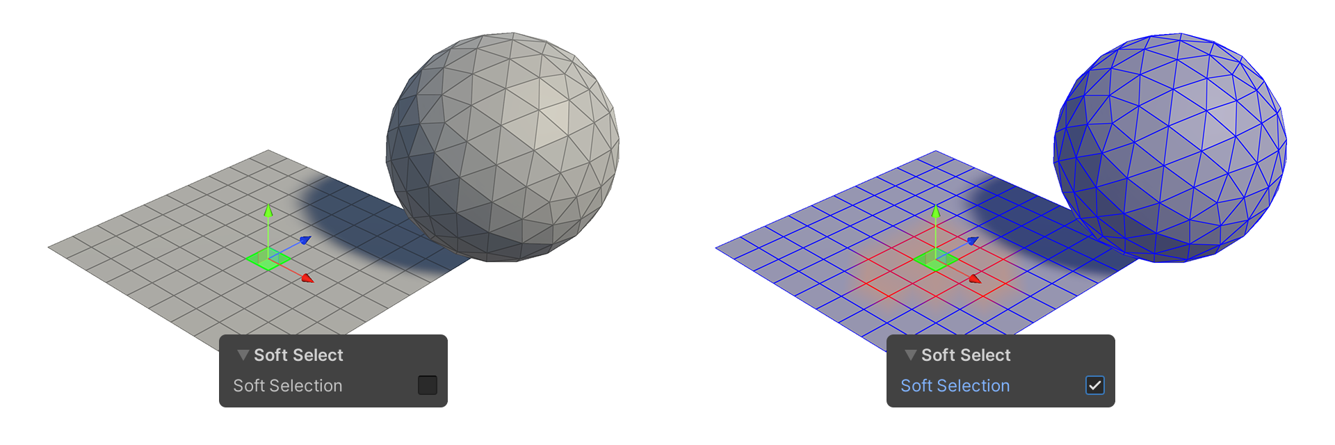
Soft Select
This property allows for the selection of elements adjacent to the selected elements in the scene (Scene), based on a weighting system.
Based on the set weight, the selected elements and the specified range are displayed in color, generally indicated by a smooth circular shape.
Soft Selection
This is a property that activates Soft Selection.
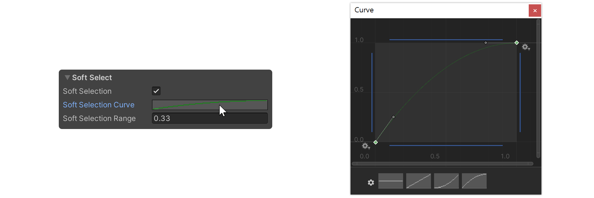
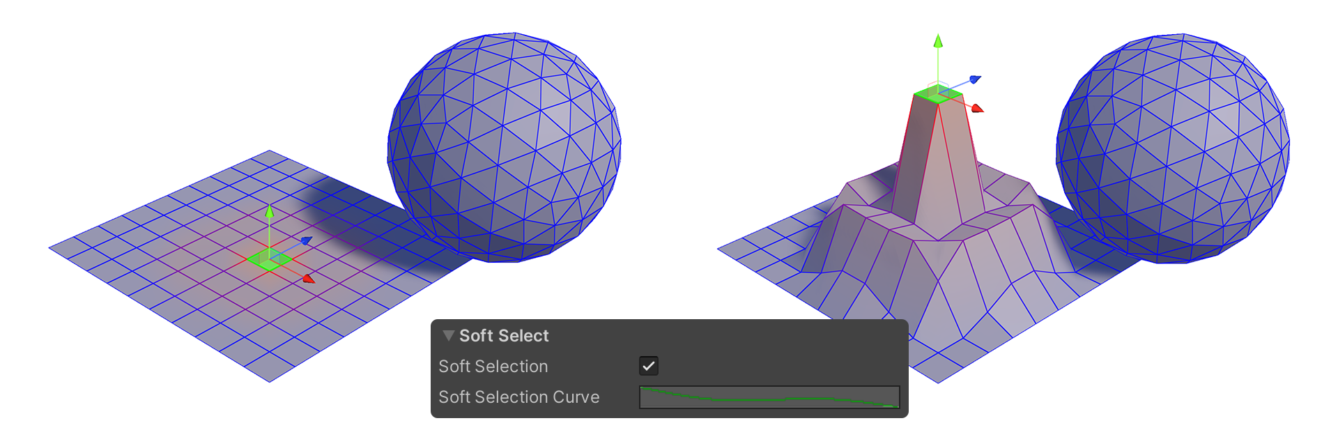
Soft Selection Curve
This property, in the form of a graph, determines the shape of the weight curve for Soft Selection. You can edit it by clicking on the graph next to the Soft Selection Curve property.
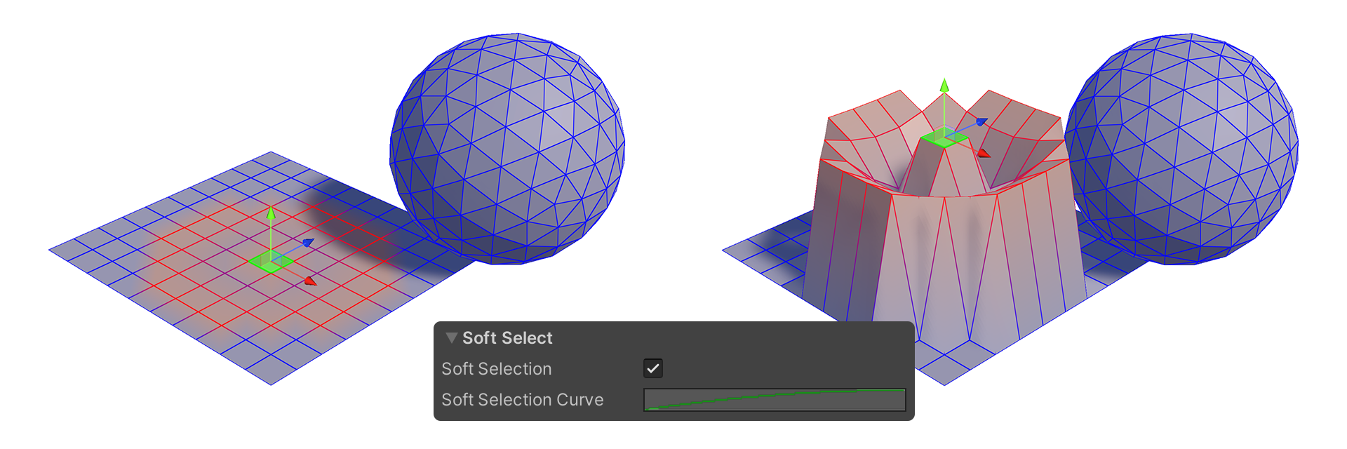
Example of Curve shape
This is an example of how the selection shape changes depending on the Curve type.
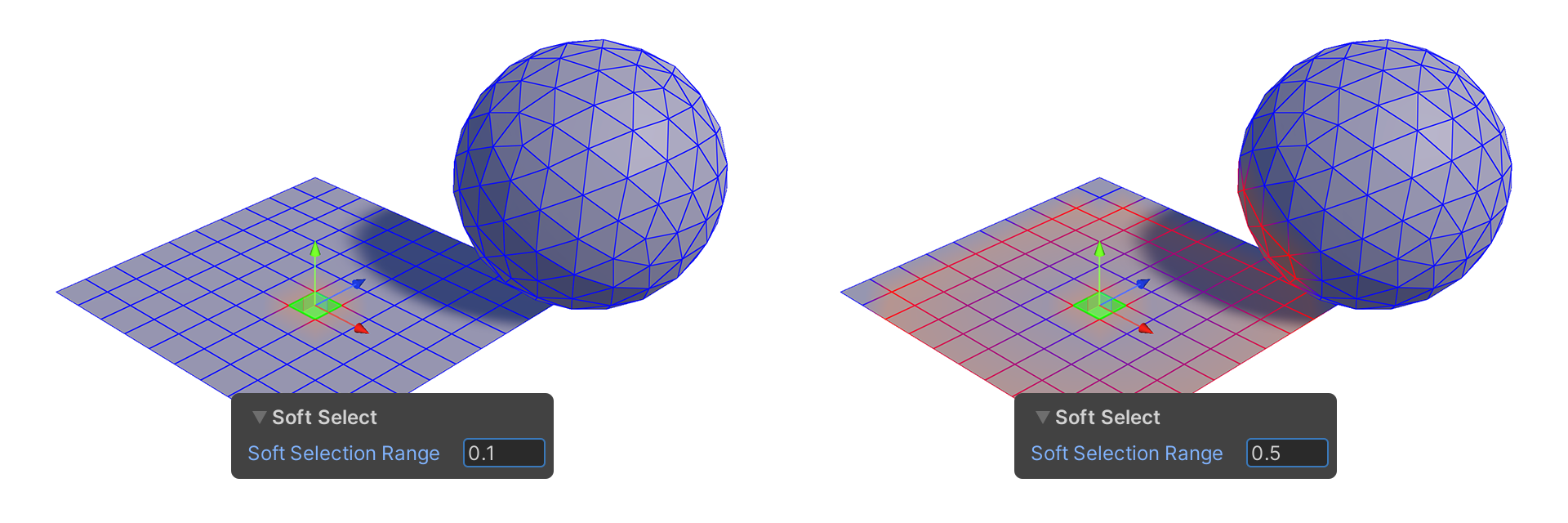
Soft Selection Range
This property sets the range over which soft selection is applied, starting from the selected elements.
Since in Unity 1 meter equals 1.0, a value of 0.5 would mean that elements up to 50cm from the selected element are selected.
Vertex Snapping
When you press the V key and move the gizmo (handle), you can move the selected element to the position of the vertex pointed by the mouse, or align the position of the element to that location.
Snap Rotation
Select a Vertex by left-clicking, then drag to rotate the object around a Pivot. The rotation aligns the selected vertex to face the direction of the Vertex closest to the mouse.
The Snapping Vertex and Degree of rotation is displayed in the GUI.
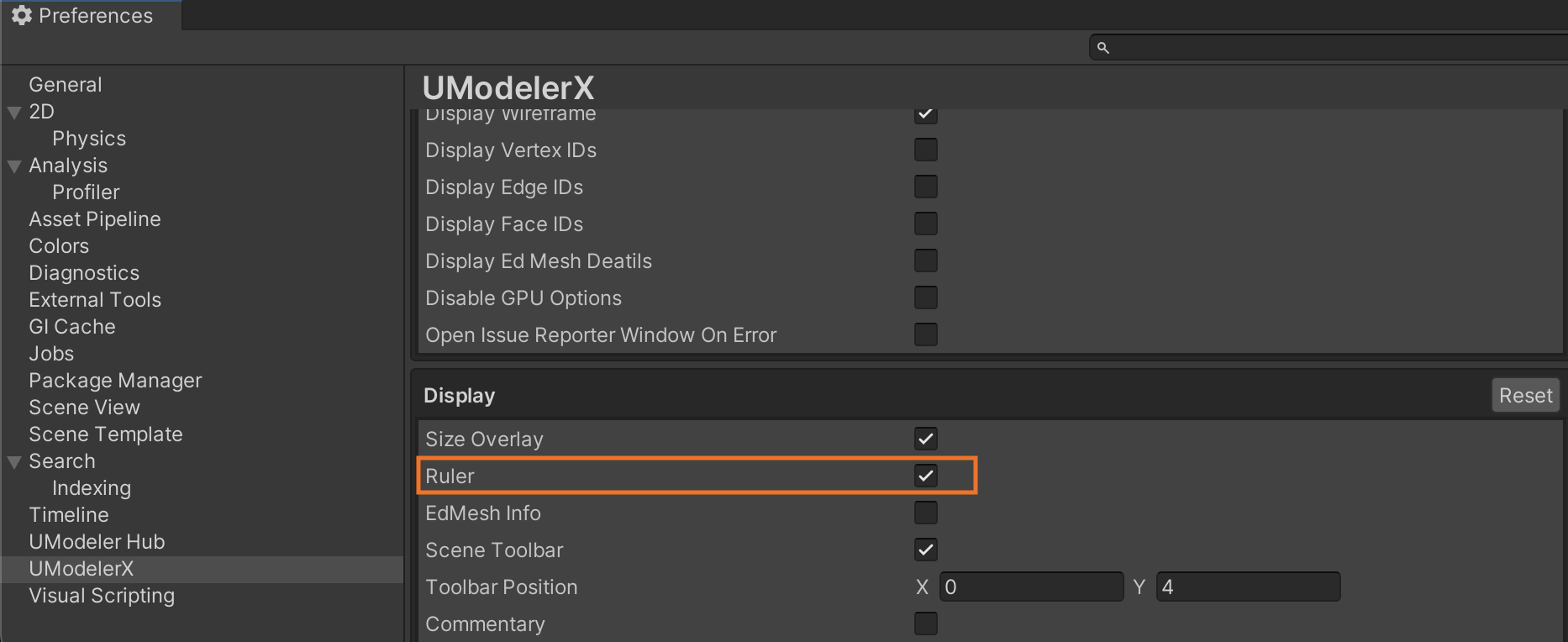
Ruler
Displays the length of the selected element. When vertices are selected, the distance between the vertices is displayed in the order selected. For edges, the length of all selected edges is displayed, and for faces, the length of all edges composing the selected faces is displayed. In the bottom right of the scene view, the total length is displayed.
The ruler can be enabled or disabled in Preferences > UModeler X > Display > Ruler property.